This project is a collaboration with RPI's Center for Mobility with Vertical Lift (MOVE) with contributions from Dr. Etana Ferede. In high speed rotorcraft applications, a large section of the retreating blade undergoes reverse flow due to a high advance ratio. Flow separation at the sharp aerodynamic leading edge during reverse flow (geometric trailing edge) leads to negative lift, pitching moment, and drag penalties. The kinematics of a rotor blade leads to a dynamic stall in reverse flow, which further accentuates the problem by causing unsteady loading. These problems have restricted the maximum forward speed of rotorcrafts to ~250 kts. Experimental study by our group has shown that these effects can be mitigated by passive deflection of the last quarter-chord of the blade in a direction opposite to that of the angle of attack, as shown in figure 1. The technique is referred to as trailing edge cambering or reflex cambering since the modification is equivalent to adding an extra camber to the blade’s last quarter chord or tail. The effectiveness of the control has been demonstrated on a 2D airfoil [1] and a cantilevered unswept blade [2], as well as on swept back and swept forward cantilevered models. For a discussion on the effects of passive cambering visit the Control of Reversed Flow in Helicopters page .
The present study focuses on the development and demonstration of an active camber morphing mechanism where the camber angle can be changed dynamically with the angle of attack. The optimal TE deflection angle, which produces lowest negative effects, is expected to vary with changing parameters such as pitch angle, azimuthal angle, and reduced frequency. The study on the cantilevered unswept airfoils showed that while a deflection angle of 15° performed better during static pitch angle in comparison to 5° and 10°, it was not optimal during certain dynamic pitch configurations [2], suggesting the need for dynamic variation of deflection angle based on kinematics. Active camber will also include variation of the deflection angle along the span of the blade. This is necessary since the velocity experienced by the blade varies along its span, where the extend of reverse flow decreases from root to tip, thus the cambering angle should also decrease accordingly. A first stage design of this model has been completed and the active camber mechanism has been tested in the wind tunnel.
Figure 2 shows the design of the prototype, where the total length of the model is 18” in span direction and 8” in chord. The prototype is equally divided into three segments along the span, as shown in Figure 2. Additionally, the bottom picture in Figure 2 shows the cross-sectional shape of the final design. Chordwise bending of the blade section is achieved by means of ‘fish-bone’ spine design in the trailing edge section (see Figure 3). The morphing section spine is made of Delrin, while the top and bottom skin are silicon rubbers 0.05’’ thick. This design has several advantages, the first of which is the reduction in bending stiffness that facilitates chordwise bending using relatively low actuation force. Second, the stringers in Figure 3 provide spanwise stiffness and preserve thickness to chord ratio during camber deformation. Lastly, the stringers provide support for the attachment of the flexible top and bottom skin. Additionally, the proposed design is relatively easy to manufacture using CNC machining. Furthermore, material is removed on each side of the airfoil section to embed the actuation rod within the prototype (see Figure 2). This will ensure the actuation rods do not interfere with the airflow over the prototype.
Figure 3 shows the actuation mechanism embedded in the camber morphing prototype design shown in Figure 2. The main spar fixes the wind tunnel model in place and is also connected to an actuator that varies the angle-of-attack of the model. The torsion rod is the component that transmits the torque from the actuator to the chordwise actuation rods. The actuation rods push (upwards or downwards) the trailing edge (TE) rod that runs through the hole of the flexible airfoil (Figure 2 and 3) located in the trailing edge region. Four chordwise actuation rods are used to deform the 18’’ long model. The design of the actuation rods, shown in Figure 4, is the result of ensuring sufficient stiffness to resist deformation under applied load ensuring that the rods remain embedded within the airfoil without compromising the structural integrity of the model.
Video 1 shows active cambering at a fixed angle of attack of the blade and Video 2 shows active cambering for a dynamically pitching blade. The pitching of the blade and the tail are not synchronized to optimum parameters in this video. Currently, further design modifications are considered which will be followed by force/moment and Stereoscopic Particle Image Velocimetry (SPIV) measurements on the finalized model.
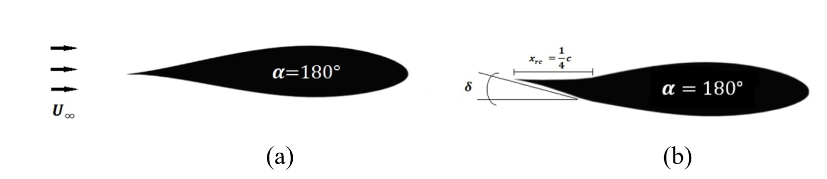
Figure 1: Schematic of NACA 63-218 airfoil used for (a) baseline, and (b) modified reflex camber models (current schematic is at a tail deflection angle of 10 degrees). The tail defection was either 5, 10 or 15 degrees. Flow is from left to right and the angle of attack is α = 180° (0° in reverse flow).
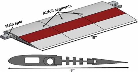
Figure 2: 3D conceptual design of the camber deformable wind tunnel model.
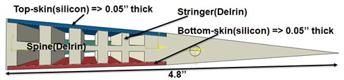
Figure 3: Segment of the deformable wind tunnel model.
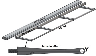
Figure 4: Design of the actuation mechanism.
Video 1: Active camber morphing at an amplitude of 5° and a frequency of 0.5 Hz about a mean camber angle of 5°. The angle of attack of the blade is 10°, the freestream velocity is 20 m/s and the flow is from right to left (reverse flow).
Video 2: Active camber morphing at an amplitude of 5° and a frequency of 0.5 Hz about a mean camber angle of 5°. The blade is dynamically pitching at an amplitude of 5° and a frequency of 0.5 Hz about a mean angle of attack of 5°. The freestr
References
[1] Jacobellis, G., Gandhi, F., Rice, T., Amitay, M., “Computational and Experimental Investigation of Camber-Morphing Airfoils for Reverse Flow Drag Reduction on High-Speed Rotorcraft”, Journal of the American Helicopter Society 65.1 (2020): 1-14.
[2] Ko, D., Guha, T. K., and Amitay, M., “Control of Reverse Flow over a Cantilevered Blade using Camber Morphing”, in press, AIAA Journal, April 2021.