

In high speed rotorcraft applications, a large section of the retreating blade undergoes reverse flow due to a high advance ratio. Flow separation at the sharp aerodynamic leading edge during reverse flow (geometric trailing edge) leads to negative lift, pitching moment, and drag penalties. The kinematics of a rotor blade leads to a dynamic stall in reverse flow, which further accentuates the problem by causing unsteady loading. These problems have restricted the maximum forward speed of rotorcrafts to ~250 kts. The present experimental study shows that these effects can be mitigated by deflecting the last quarter-chord of the blade in a direction opposite to that of the angle of attack, as shown in figure 1. The technique is being referred to as trailing edge cambering or reflex cambering since the modification is equivalent to adding an extra camber to the blade’s last quarter chord or tail. Experiments consisted of flow field measurements using Stereoscopic Particle Image Velocimetry (SPIV) and force/moment measurements using a load cell, which were conducted on a NACA 63-218 airfoil. The effectiveness of the control has been demonstrated on 2D [1] and cantilevered unswept [2] airfoils, as well as on swept back and swept forward cantilevered models.
Trailing edge deflection yields a significant reduction of flow separation at the sharp leading edge at both unswept (figure 2) and swept configurations (figure 3). It also results in a reduction in the size of the wake. A smaller separation bubble means lower suction from the low pressure vortex core, leading to smaller negative lift and pitching moment. Correspondingly, lower negative lift (figure 4a) and pitching moment (figure 4b) are observed for the cambered airfoils in the region of 180°< α <190°. After open separation on the baseline airfoil, the low pressure core moves away from the surface leading to lower negative lift and moment, whereas it keeps on increasing for the attached bubble of the cambered airfoil. Correspondingly, negative lift and pitching moment are higher for the cambered airfoils beyond the point of baseline open separation, α > 190°. The drag coefficient (figure 4c) is lower for the cambered airfoils in the entire reverse flow region, α > 180°, due to reduced separation and a smaller wake. Extensive load cell measurements were conducted to study the hysteresis during dynamic pitching at different pitching frequencies, amplitudes and mean angles of attack. The hysteresis is caused by the growth and advection of the separation bubble, and variations in the flowfield between pitch up and pitch down motions. Reduction in the size of the separation bubble and the wake led to a mark reduction in the hysteresis levels, with cambering. Figure 5 shows an exemplary case where very high levels of hysteresis are observed for the baseline airfoil and significant reduction is observed with trailing edge cambering of 10°. Similar reduction levels were also observed with cambering of 5° and 15°.

Figure 1: Schematic of NACA 63-218 airfoil used for (a) baseline, and (b) modified reflex camber models (current schematic is at a tail deflection angle of 10°). The tail defection was either 5°, 10° or 15°. Flow is from left to right and the angle of attack is α = 180° (0° in reverse flow).
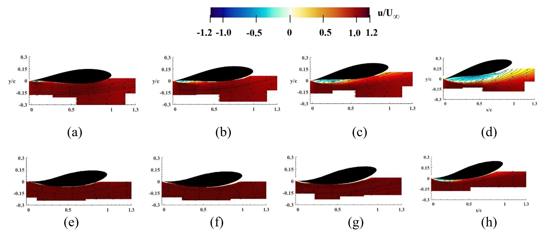
Figure 2: Color contours of centerline time-averaged streamwise velocity, superimposed with in-plane streamlines, at different static pitch conditions for the baseline (a, b, c, d), and 10° cambered (e, f, g, h) unswept cantilevered models at α = 184° (a, e), 187° (b, f), 190° (c, g), and 194° (d, h). Flow is from left to right.
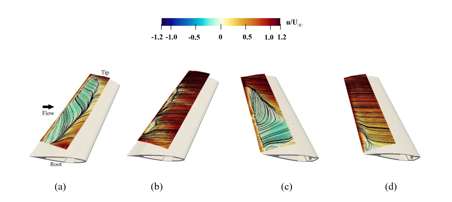
Figure 3: Color contours of normalized chord-parallel velocity, superimposed with in-plane streamlines, on a surface that is parallel to the blade surface and very near to it. Baseline blade (a, c), and 10° cambered blade (b, d), at backward sweep angle of 20° (a, b) and forward sweep angle of -20° (c, d). The angle of attack is α = 190° and flow is from left to right.
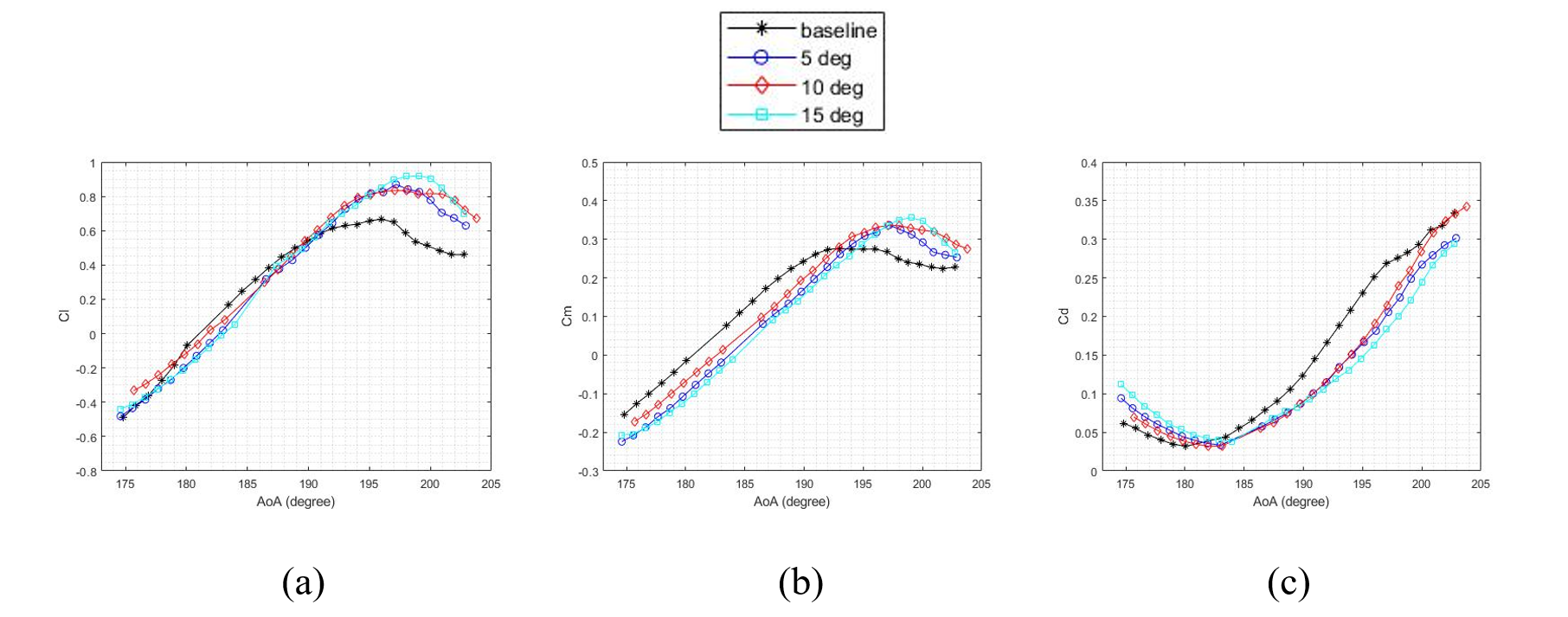
Figure 4: Comparison of the variation of the lift coefficient (a), pitching moment coefficient (b), and drag coefficient (c) with angle of attack, between the baseline, 5°, 10°, and 15° cambered models.
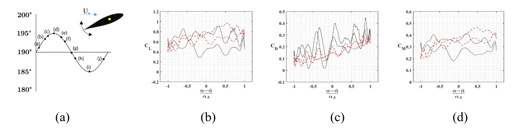
Figure 5: Variation of lift (b), drag (c), and pitching moment (d) coefficients during dynamic pitch at an amplitude of 5° about a mean angle of attack of 195.5°. The frequency of oscillation is 1.14 Hz corresponding to a reduced frequency of kf = 0.05. A schematic of the oscillation is shown in (a).
References
[1] Jacobellis, G., Gandhi, F., Rice, T., Amitay, M., “Computational and Experimental Investigation of Camber-Morphing Airfoils for Reverse Flow Drag Reduction on High-Speed Rotorcraft." Journal of the American Helicopter Society 65.1 (2020): 1-14.
[2] Ko, D., Guha, T. K., and Amitay, M., “Control of Reverse Flow over a Cantilevered Blade using Camber Morphing,” in press, AIAA Journal, April 2021.