This project is an experimental investigation of separated flows over cantilevered wings with a cross-section NACA 0015. The goal of this research is to link changes in the separated flow field to variations in aspect ratio, angle of attack, Reynolds number, sweep angle, and taper ratio. The results include qualitative surface topology from oil flow visualization, quantitative flowfield measurements using Stereo Particle Image Velocimetry (SPIV) and Time-Resolved Stereo Particle Image Velocimetry.
Flow visualizations of swept and tapered models with semi-aspect ratios (sAR) of 2, and taper ratios = 0.269 shown in Figure 1 and Figure 2. In Figure 1, the taper ratio is achieved by sweeping the trailing edge forward and leading is unswept. In Figure 2, the leading edge is swept aft and the trailing edge is unswept. As angle of attack is increased, a spiral forms on the surface of each wing, however, for the trailing edge swept case the spiral evolves towards the root and for the leading edge swept case the spiral evolves towards the tip. A snapshot of the SPIV measurements of the same wing geometry at a much lower Reynolds number shows the 3D evolution of this spiral for each case.
The volumetric mean velocity field over a purely swept wing (leading and trailing edges swept aft 30 degrees) measured with SPIV is presented in Figure 3. The contours of the normal Reynolds stress components show that large fluctuations of velocity are present near the spiral that forms on the surface of this wing. A similar spiral also forms on the surface of a wing with its quarter chord line swept aft 30 degrees with a taper ratio of 0.269 (see video). These insights into the formation of the separated flowfields at different wing geometries will be used to inform ultra-efficient flow control techniques.
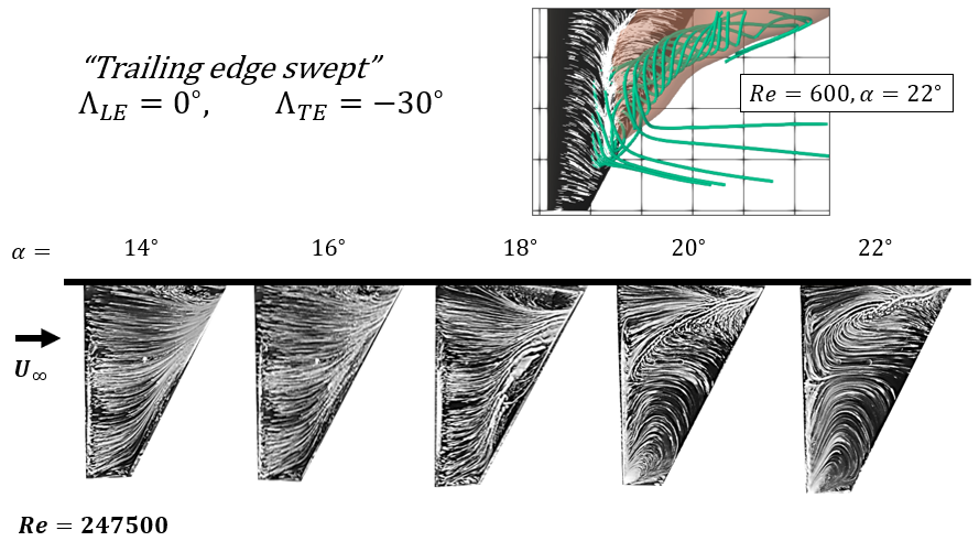
Figure1: Oil flow visualization of tapered wing with trailing edge swept forward at different angles of attack
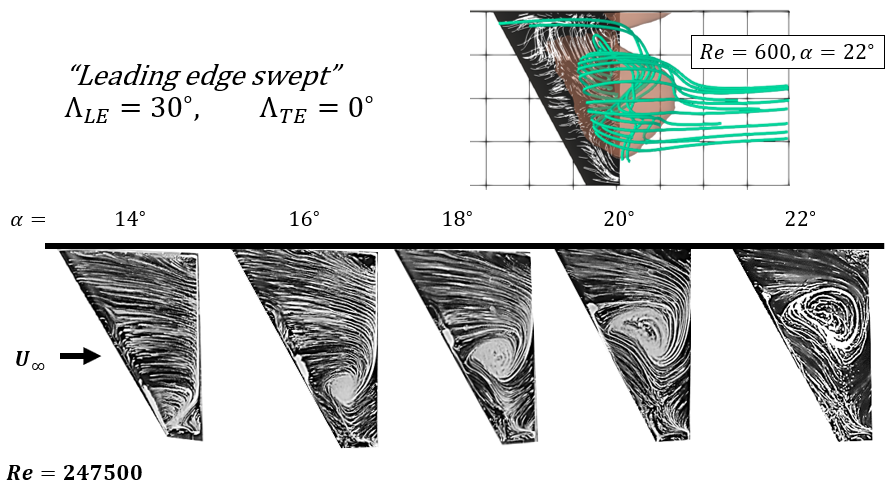
Figure 2: Oil flow visualization of a tapered wing with leading edge swept back at various angles of attack.
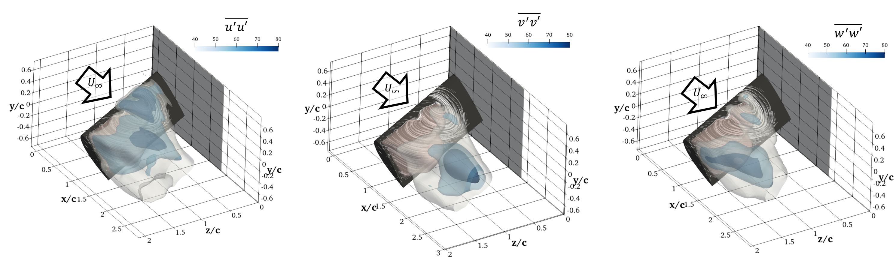
Figure 3: Normal Reynolds stresses in streamwise (left) vertical (middle) and spanwise (right) velocity components as measured with SPIV.
Selected Publications
- Neal, J. M., & Amitay, M. Three-dimensional separation over unswept cantilevered wings at a moderate Reynolds number. Physical Review Fluids, 014703(8), 1–24.(2023). https://doi.org/10.1103/PhysRevFluids.8.014703
Presentations
- Carvajal T.R., Neal J., Amitay M., “Evaluation of the Modified Version of the Holmn Vortex Identification Method Using Experimental Data” AIAA Scitech, National Harbour, MD, 23rd 27th, Jan. 2023
- Neal J., Amitay M. “Experimental investigation of 3-D separation over swept and tapered wings at a moderate Reynolds number”, 75th Meeting of the American Physical Society, Division of Fluid Dynamics, Indianapolis, IN, November 22 2022
- Neal J. and Amitay, M., “Three-Dimensional Flowfield Measurements of a Swept-back Cantilevered Wing at High Angles of Attack.” AIAA Scitech, San Diego, CA, 3rd 7th, Jan. 2022
- Neal, J. and Amitay, M., “Three-Dimensional Separation Over Low Aspect Ratio Cantilevered Wings.” AIAA-2021-1212, SciTech, Virtual event, 11-15; 19-21, January 2021
- Neal J., Amitay M. “Three-dimensional separation over a finite-span NACA 0015 airfoil”, 72nd Meeting of the American Physical Society, Division of Fluid Dynamics, Seattle, WA, November 23 2019