This project focuses on the development and application of piezoelectric linear actuators in different examples of active flow control. The primary goal of this research is to build and quantify custom piezoelectric bending beam actuators; the piezoceramic used is Lead Zirconate Titanate. Different actuators with varying parameters such as piezoelectric thickness and beam length are being fabricated and tested. These devices are actuated with a periodic function, resulting in an oscillating platform on which to mount different flow control devices. The main quantification method consists of driving these devices through voltage and frequency sweeps to obtain displacement values on frequency response curves. Other quantification methods include measuring the actuator’s blocking force and static displacement under a fixed voltage. In addition to physical testing of these devices, an analytical model based on the design parameters is being developed, and was verified with the obtained experimental data. Finite element analysis and life cycle testing were also performed.
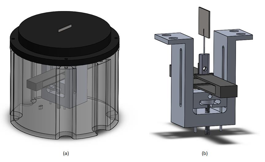
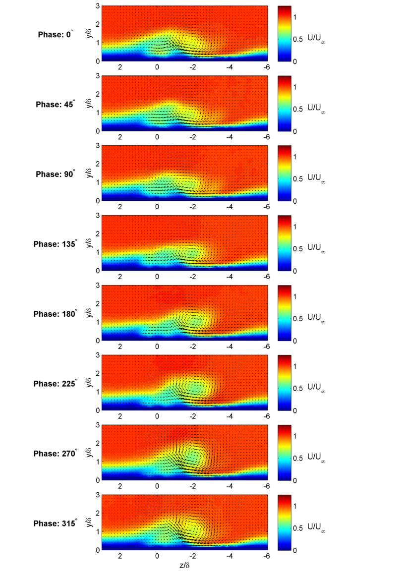
The second objective of this project is to utilize the piezoelectric actuators as active flow control devices in different wind tunnel tests. One example is the use of these actuators to drive dynamic vortex generators (DVGs). Traditional static vortex generators (SVGs) are mounted on aircraft to bring high momentm flow into the boundary layer to delay flow separation. Dynamic vortex generators have the ability to oscillate up and down, possibly being more effective than static VGs by providing additonal momentum and exciting inherent instabilities in the flow field. They can be deployed only when needed and retracted when not in use, resulting in less overal drag during cruise. Under this project, SVGs and piezoelectrically driven DVGs with varying mean hights are being tested over a flat plate and compared. Figure 1 shows a CAD rendering of the VG module; (a) shows the external view of the module while (b) shows the internal mechanism. Below it, in Figure 2, is an example of Stereo Particle Image Velocimetry (SPIV) results of the DVG in action.
The second objective of this project is to utilize the piezoelectric actuators as active flow control devices in different wind tunnel tests. One example is the use of these actuators to drive dynamic vortex generators (DVGs). Traditional static vortex generators (SVGs) are mounted on aircraft to bring high momentum flow into the boundary layer to delay flow separation. Dynamic vortex generators have the ability to oscillate up and down, possibly being more effective than static VGs by exciting inherent instabilities in the flow field. They can additionally be deployed only when needed and retracted when not in use, resulting in less overall drag during cruise. Under this project, SVGs and piezoelectrically driven DVGs with varying mean heights are being tested over a flat plate, and will be compared. This CAD rendering shows the configuration of the DVG module mounted on a flat plate.
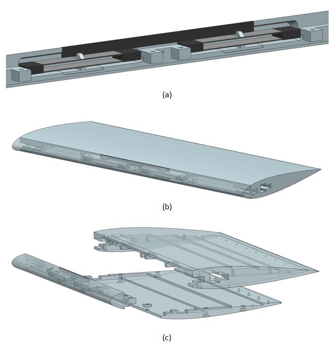
The piezoelectric beam actuators are also involved in a project in collaboration with the Air Force Office of Scientific Research investigating the phenomenon of stall cells. The actuators are being used to drive a spanwise-oriented dynamic trip mounted on an airfoil in an attempt to generate stall cells in flow conditions where they do not naturally occur. This application takes advantages of these devices’ ability to actuate quickly and consistently. This image shows a CAD rendering of the stall cell airfoil.
DVG Phase-Locked PIV Flow Fields

Figure 1: DVG module: (a) external view; (b) internal mechanism

Figure 2: SPIV DVG plots
The piezoelectric beam actuators are also involved in a project in collaboration with the Air Force Office of Scientific Research investigating the phenomenon of stall cells. The actuators are being used to drive a spanwise-oriented dynamic trip mounted on an airfoil in an attempt to generate stall cells in flow conditions where they do not naturally occur. The goal is to observe the transient formation of stall cells using SPIV to gain a greater understanding of the phenomenon. This application takes advantage of these devisces' ability to actuate quickly and consistently. Figure 3 shows a CAD rendering of the stall cell airfoil; (a) shows the actuator configuration in the airfoil, (b) shows the assembled view of the airfoil, and (c) shows the exploded view of the airfoild assembly.

Figure 3: Stall cell airfoil; (a) actuator intergration; (b) assembled airfoil; (c) exploded view of assembly