

The inlet to an aircraft propulsion system is typically designed to supply flow to the compressor with minimal pressure loss, distortion, or unsteadiness. Otherwise, the overall system performance will be reduced, which can result in stall or surge of the compressor and a catastrophic failure of the engine. While the inlet length required to avoid separation and its associated losses may not be a significant design driver for some aircraft, other applications require a short inlet length due to integration and packaging constraints, and others because the inlet length can drive the size of the overall aircraft (i.e., production and operating costs). Therefore, technologies such as passive or active flow control that can enable shorter inlets could have significant overall system benefits.
Current aircraft designs typically consider the compressor and inlet as separate subsystems, where the connection between them is given as a pressure recovery and distortion specification that must be met at the Aerodynamic Interface Plane (AIP). As is expected of an aircraft intake, the flow must be decelerated whilst achieving as a uniform flow as possible at the compressor face with minimum stagnation pressure loss. Short inlets have high degree of centerline curvature. Due to centerline curvature, there are cross-stream pressure gradients resulting in migration of boundary layer fluid in the direction of the pressure gradient giving rise to secondary flows. Within the boundary layer, this imparts cross-flow velocities creating non-uniform total pressure profiles. In addition, there is a streamwise pressure gradient resulting from the increased cross-sectional area. The combined effect results in distortion and total pressure loss at the inlet exit, which is clearly undesirable.
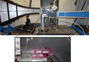
The present research focuses on the effectiveness of active flow control (via steady and unsteady control jets) in an aggressive inlet duct (L/D =1.5) at a Mach number of 0.45. This is a Multidisciplinary research effort, involving experiments, numerical simulations, and modeling and control. The experimental investigation includes the effect of flow control actuators, placed at streamwise locations where the flow was expected to separate, Figure 1). Two modes of actuation were tested: steady blowing and unsteady blowing with frequencies between 350Hz and 1200Hz. In addition, the effect of the blowing ratio (at a fixed momentum coefficient) was addressed by changing the area of the control jet exit.
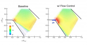
In order to explore the interaction between the control jets and the main flow, PIV measurements were conducted in the vicinity of the upstream control jet. Figure 2 present the velocity vector fields colored by the total velocity magnitude, where Figures show the velocity vector field in the vicinity of the upstream jet, with and without flow control. Without flow control (left plot), the flow separates immediately downstream of the turn and stays separates throughout the remainder of the measurement domain. When flow control is applied (right plot) the separation regime is completely mitigated.